flowful-ai
Install Parametric 3d Printing
Pick your agent. Every command is ready to paste.
npx skills add flowful-ai/cad-skillThe open skills CLI detects your agents (Claude Code, Cursor, Codex and 70+ more) and installs to the right folder. Add -g to install globally.
01
Install it
Run the command above, or upload the folder in Claude.
02
Ask naturally
Describe the task. Your agent loads parametric-3d-printing when the request matches its description.
03
Name it if needed
If it does not trigger, say “use the parametric-3d-printing skill”. In Codex, type $parametric-3d-printing.
Parametric 3D Printing with CadQuery
Overview
This skill generates parametric 3D models using CadQuery (Python) and exports them as STL files ready for slicing. CadQuery is preferred because it installs via pip, has a Pythonic API, and handles complex geometry (fillets, chamfers, booleans, assemblies) better than alternatives.
Setup
CadQuery requires Python 3.10-3.12 (the OCC kernel lacks 3.13+ wheels). Run from this skill's directory. With uv, which downloads Python 3.12 if the machine lacks it:
uv venv --python 3.12 && source .venv/bin/activate
uv pip install -r requirements.txt
Without uv, when Python 3.10-3.12 is already installed:
python3.12 -m venv .venv && source .venv/bin/activate
pip install -r requirements.txt
CadQuery uses the OpenCASCADE kernel under the hood. trimesh, pyrender, Pillow, and numpy are used for the preview-analyze-iterate loop; lxml is required by the 3MF writer (stl_to_3mf.py). No display server is needed; everything renders headlessly via pyrender's offscreen backend.
If CadQuery fails to install (OCC kernel build errors), try:
# Option 1: Use conda (CadQuery's officially recommended method)
conda install -c cadquery -c conda-forge cadquery

# Option 2: Use the pre-built wheels
pip install cadquery --find-links https://github.com/CadQuery/CadQuery/releases
Real-World Dimension Research
When designing objects that interface with real products (phones, chargers, PCBs, connectors, etc.), use web search to find accurate dimensions before writing any geometry code. Don't guess or use approximate values. Even 1-2mm off can make a part unusable.
What to research:
- Connector/port dimensions (USB-C: 8.4 x 2.6mm opening, Lightning, barrel jacks)
- Device dimensions (phone width/thickness, PCB footprints, charger puck diameters)
- Mounting hole patterns and screw sizes (M2.5, M3, etc.)
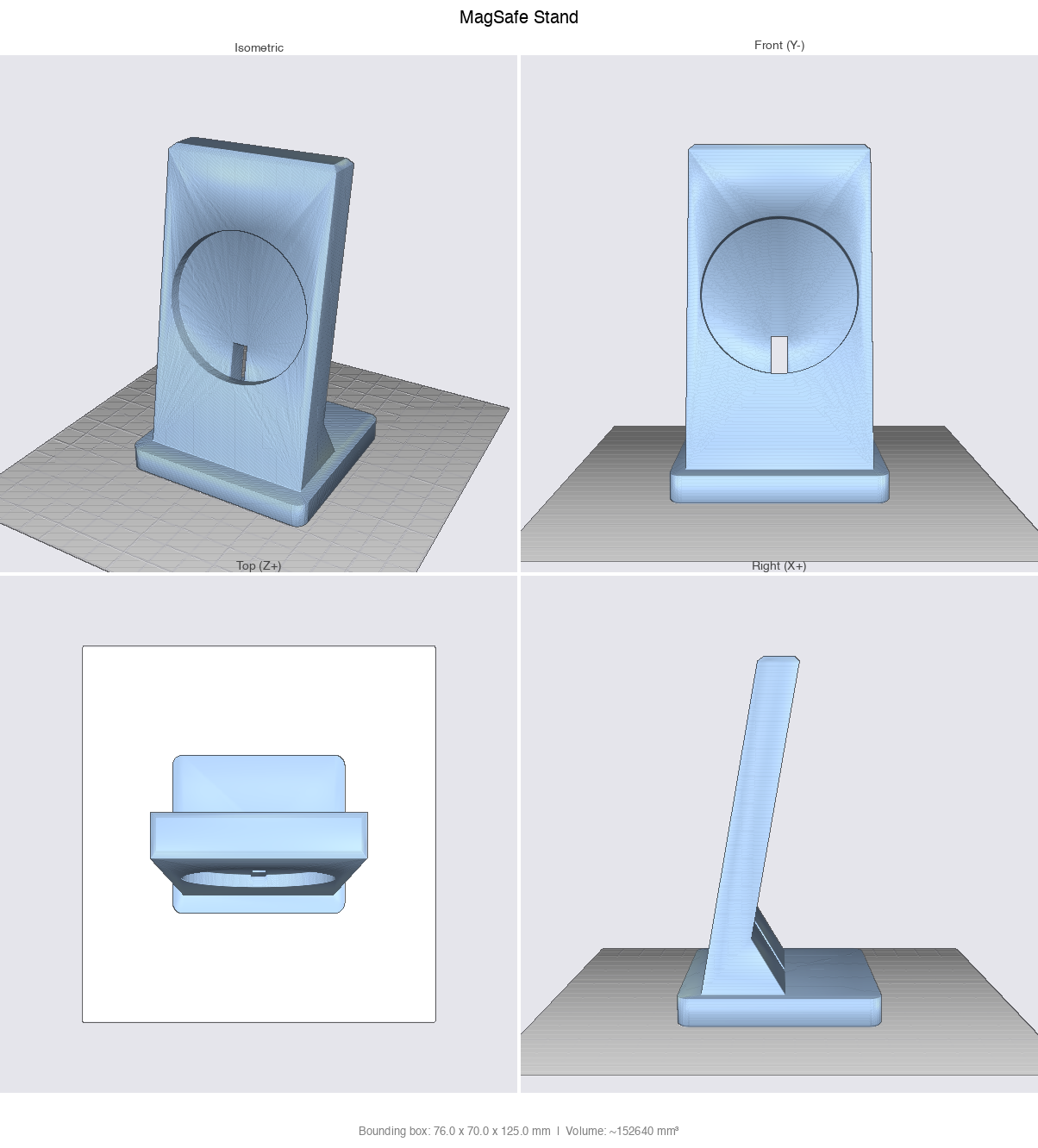
- Standard component specs (MagSafe puck: 56mm diameter, 5.6mm thick)
- Cable bend radii and strain relief requirements
How to use it:
- Search for "[product] dimensions mm" or "[component] datasheet"
- Cross-reference at least 2 sources when precision matters
- Add the sourced dimensions as comments in the PARAMETERS section:
# MagSafe puck dimensions (source: Apple spec + iFixit teardown) puck_diameter = 56.0 # mm puck_thickness = 5.6 # mm - When in doubt, add 0.3-0.5mm clearance to external dimensions
This is especially important for: phone cases/stands, charger mounts, PCB enclosures, cable management, adapter fittings, and anything that clips onto or wraps around an existing product.
Measuring from photos
When the thing to fit is in the user's home (a hole, a frame, a pipe), ask for a photo with a tape measure laid across it, one per axis. A photo often answers more than the number:
- Read the tape where the object ends, not where the hook sits. The hook is zero; check the hook is actually on the object's edge.
- Read the brand and model off the object (moulded logos, labels). A product that matches the measured size gives you the spec sheet values for hidden dimensions, like the cut-out behind a frame. Use the measurement to confirm the model, and the spec for what the tape can't reach.
- Look at the surroundings: distance to a floor, hinge or wall, paint shadows of an older fitting, existing screw holes. They bound how far the part can extend.
- Ask for the one measurement only the user can take (the hole once the old part is off, a door thickness) and keep that dimension a named parameter so it can be corrected before printing.
Core Workflow
- Gather requirements (see Requirements Gathering below)
- Research dimensions of any real-world products involved (see above)
- Phase 1, Base shape: Build outer shell, preview, get user feedback
- Phase 2, Features: Add functional details, preview, get user feedback
- Phase 3, Final delivery: Fillets, cleanup, final preview + STL + print recommendations
- Offer parameter tweaks after delivery
This is a collaborative, show-as-you-go process. Do NOT disappear and come back with a finished model. Show the user your progress at each phase and incorporate their feedback before moving on.
Requirements Gathering
Before writing any code, walk through these topics with the user conversationally. Don't dump all questions at once. Ask the most important ones first, then follow up based on answers. Use reasonable defaults when the user doesn't specify.
What is it? Object type, purpose, what it holds/protects/attaches to. Get a clear mental model of the object before anything else.
Critical dimensions Must-fit measurements, like PCB size, phone width, screw spacing, diameter of the thing it wraps around, etc. These are non-negotiable and drive everything else.
Mounting & attachment How does it connect to things? Screws (what size?), snap-fit, adhesive tape, magnets, freestanding on a desk? This affects wall thickness, boss placement, and overall structure.
Printer & material
What printer do they have? (Bambu, Prusa, Ender, etc.) Nozzle size? Material (PLA, PETG, TPU)? This directly affects tolerances, minimum feature sizes, and design constraints. Defaults: 0.4mm nozzle, PLA, 0.2mm layer height. The printer also sets the build volume: pass it to the run wrapper with --bed (see below) as soon as the part is larger than about 150mm, so an oversized part fails in the loop instead of in the slicer.
Functional needs Ventilation/airflow, water resistance, cable routing, access panels, visibility windows, stacking, weight limits. Ask only what's relevant to the object.
Aesthetic preferences Rounded vs sharp edges, minimal vs industrial look, color considerations (affects visibility of layer lines). Ask briefly. Most users care more about function than form.
Start with the first two (what + dimensions), then ask about mounting and material if relevant. Only ask about aesthetics if the user seems to care or if it affects structural choices.
When a question tool is available, ask the questions that change the design in one batch, each with the typical answers as options (common product sizes from your research, the usual mounting methods). Users answer a list of concrete options faster than open questions, and "Other" still lets them type a measurement.
Progressive Preview Workflow
Build the model in phases. At each phase, export an STL, render a preview, self-review it, then show it to the user and ask for feedback before proceeding. This catches problems early and keeps the user involved.
Preview recipe (use at every phase)
One-shot (run script + render + parse result as JSON):
python3 run_cadquery_model.py model.py --preview --strict --bed a1
This executes model.py, finds the STL it wrote, renders the multi-view preview, and emits a JSON result with success, stdout, stderr, stl, preview, watertight, bboxes (measured X/Y/Z of each STL, in mm) and fits_bed. With --strict, a non-watertight mesh is a hard failure. With --bed, a part that does not fit the build volume (90° rotation allowed, 5mm kept free per side) is a hard failure; it takes a printer name (a1, a1mini, p1s, x1c, h2d, mk4, mini, core1, ender3, k1, full list in mesh_io.PRINTER_BEDS) or WxDxH in mm. Use this as the default loop: if success is false, read the stderr field to fix the CadQuery script, then re-run. Compare bboxes with the dimensions you meant to build.
Rendering only (when the STL already exists):
python3 preview.py model.stl preview.png --views multi
Then view the preview image, self-review it against the checklist in design-review.md, and fix any issues you spot before showing it to the user.
Phase 1: Base Shape
Build the basic outer form: overall dimensions, shell/walls, bottom plate. No cutouts, no fillets, no details yet.
- Write the script with parameters and basic geometry
- Export STL and render preview
- Self-review: Does the shape and size look right? Is the bottom flat for printing?
- Show the preview to the user: "Here's the basic shape. Does this look right before I add details?" Include key dimensions.
- Wait for feedback. If the user wants changes, iterate here before moving on.
Phase 2: Features
Add functional details: holes, cutouts, mounting bosses, cable slots, ventilation, snap-fits, internal structures.
- Add features to the script
- Export STL and render preview
- Self-review: Are all features visible? Do booleans look clean? Are holes in the right positions?
- Show the preview to the user: "I've added [list features]. Anything to change before I finalize?"
- Wait for feedback. Iterate if needed.
Phase 3: Final Delivery
Apply finishing touches: fillets, chamfers, edge cleanup. Do a full printability review.
- Add fillets/chamfers (largest radius first, apply after shell)
- Export final STL and render preview
- Full self-review using the complete checklist from
design-review.md: visual inspection, dimensional verification, printability analysis - Fix any issues found, re-export if needed
- Deliver to the user: final STL + preview image + print recommendations (orientation, supports, infill, material notes)
Important: Do NOT skip phases or combine them unless the model is very simple (e.g., a flat bracket with two holes). For anything with enclosed geometry, multiple features, or tight tolerances, follow all three phases.
Read design-review.md for the full visual inspection checklist, dimensional verification code, and printability analysis helpers.
Print Recommendations (final delivery)
When you deliver the final STL, always include a one-line slicer recipe plus a short rationale. Bambu Studio, PrusaSlicer, and OrcaSlicer already set sensible defaults from their filament + process presets, so do not restate every slicer option. Only tell the user what matters for this model: material, layer height, walls, infill, supports, and orientation. Tweak from the baseline below only when the model needs it.
Baseline recipe (0.4mm nozzle, typical FDM):
PLA, 0.2mm layer, 2 walls, 15% gyroid infill, no supports, orientation: flat side on bed.
When to deviate from the baseline:
- Load-bearing brackets / hooks / hinges: bump infill to 25-40%, 3-4 walls, consider PETG over PLA for toughness.
- Thin decorative walls or vases: 0 infill, vase mode or 1 wall.
- Tall narrow parts: add a brim for bed adhesion.
- Large flat parts (plates, panels over ~150mm): corners lift as PLA cools. Brim or mouse ears, PETG if the room is cold, and stiffen with ribs instead of a thicker plate (a thick solid plate warps harder and costs more filament).
- Flexible parts (gaskets, grips): TPU 95A, 0.2mm layer, slower speed, no supports.
- Functional overhangs the geometry can't avoid: tree supports, or call them out so the user knows.
- Outdoor / hot environments: PETG or ASA, not PLA.
- Food / skin contact: call out that FDM parts are not food-safe and recommend a food-safe coating.
Format at delivery time:
Print settings: PLA, 0.2mm layer, 2 walls, 15% gyroid infill, no supports.
Orientation: place flat back side on the bed (front face up).
Why: the case has no overhangs above 45°, and 15% infill is plenty for a
TPU-adjacent protective shell.
Keep it to ~3 lines. Never dump every slicer setting; the slicer already knows.
Script Template
ALWAYS structure scripts like this:
import cadquery as cq

# ============================================================
# PARAMETERS - Edit these to customize the model
# ============================================================
# Overall dimensions
width = 60.0        # mm - outer width
depth = 40.0        # mm - outer depth
height = 25.0       # mm - outer height

# Wall and structural
wall = 2.0          # mm - wall thickness (min 1.2 for FDM)
corner_r = 2.0      # mm - corner fillet radius

# Tolerances
fit_clearance = 0.3 # mm - clearance for press-fit (adjust per printer)

# ============================================================
# MODEL
# ============================================================
result = (
    cq.Workplane("XY")
    .box(width, depth, height, centered=(True, True, False))
    # ... build geometry using parameters above (bottom at Z=0)
)

# ============================================================
# EXPORT
# ============================================================
# Use tolerance=0.01, angularTolerance=0.1 for consistent tessellation
# across models. Defaults give coarser, wildly variable STL sizes.
cq.exporters.export(result, "output.stl",
                    tolerance=0.01, angularTolerance=0.1)
print(f"Exported: {width}x{depth}x{height}mm")
Key Rules
Parameters First
- ALL dimensions go in the PARAMETERS section at the top
- Use descriptive names:
screw_hole_d, notd1 - Add units in comments (always mm)
- Group related parameters with blank lines and section comments
Print-Friendly Defaults
Key FDM design defaults:
| Property | Minimum | Recommended |
|---|---|---|
| Wall thickness | 1.2mm | 2.0mm |
| Layer height | 0.08mm | 0.2mm |
| Hole clearance | 0.2mm | 0.3mm |
| Press-fit interference | 0.1mm | 0.15mm |
| Min feature size | 0.4mm (nozzle) | 0.8mm |
| Fillet radius (bottom) | 0.5mm | 1.0mm |
| Bridge span | - | < 20mm unsupported |
| Overhang angle | - | < 45 degrees from vertical |
Material-specific adjustments: TPU needs larger clearances (~0.5mm) due to flex. PETG is stickier, so add +0.1mm to fit clearances. ABS shrinks ~0.5-0.7%, so scale critical dimensions up slightly. When in doubt, print a small test piece first.
Orientation Awareness
- Design with print orientation in mind
- Flat bottom surfaces print best
- Avoid supports when possible by designing around overhangs
- Add chamfers to bottom edges instead of fillets (fillets need supports)
- Comment the intended print orientation in the script
CadQuery Patterns
Common patterns to know:
Hollow enclosure (boolean subtraction, preferred):
outer = (
    cq.Workplane("XY")
    .box(width, depth, height, centered=(True, True, False))
    .edges("|Z").fillet(corner_r)
)
inner = (
    cq.Workplane("XY")
    .workplane(offset=floor_t)
    .box(width - 2*wall, depth - 2*wall, height, centered=(True, True, False))
    .edges("|Z").fillet(max(0.1, corner_r - wall))
)
result = outer.cut(inner)
Screw boss:
.pushPoints([(x, y)])
.circle(boss_od / 2).extrude(boss_h)
.pushPoints([(x, y)])
.hole(screw_d + fit_clearance)
Snap-fit clip:
# Cantilever beam with overhang hook
.workplane(offset=wall)
.moveTo(x, y).rect(clip_w, clip_l).extrude(clip_h)
# Add hook at tip with a small overhang (< 45 deg)
Ventilation grid:
.pushPoints(vent_positions)
.slot2D(slot_l, slot_w).cutThruAll()
Adhesive-mounted cover or panel (VHB tape):
- Leave a flat, unbroken contact band at least 20mm wide where the tape goes; VHB rolls are 12, 19 or 25mm wide. No ribs, text or chamfers inside that band.
- Tape holds well in peel and tension but creeps under a constant sideways load. When the part covers a hole, add a hollow locating plug on the back that drops into the hole with 1-1.5mm clearance per side: it centres the part while the tape is applied and takes any knock sideways. Keep its depth under half the substrate thickness if a twin part goes on the other side.
- Print the visible face down on the bed for the smoothest finish, with a small chamfer on that edge (fillets on the bed edge need supports).
- See
examples/cat_flap_cover.py.
Other patterns: mounting brackets, cable routing channels, text/labels (.text()), multi-part assemblies with alignment pins.
Common Pitfalls
- Hollowing: prefer boolean subtraction over
.shell()..shell()is fragile. It fails on tapered bodies, lofted shapes, unions of multiple primitives, and anything with many fillets. The reliable pattern is:
Only reach forouter = cq.Workplane("XY").box(w, d, h, centered=(True, True, False)).edges("|Z").fillet(corner_r) inner = ( cq.Workplane("XY") .workplane(offset=floor_t) .box(w - 2*wall, d - 2*wall, h, centered=(True, True, False)) .edges("|Z").fillet(max(0.1, corner_r - wall)) ) result = outer.cut(inner).shell()when the body is a single simple primitive (one.box()or.cylinder()) with a uniform wall thickness on all sides. If in doubt, use boolean subtraction. - Build order: fillet → cut, not cut → fillet. Apply fillets while the geometry is still a clean primitive. Once you have cut holes/slots/pockets into a body, filleting the resulting edges often fails or produces bad geometry. Same rule for chamfers.
- Fillet failures: Apply fillets from largest to smallest radius. Do not wrap fillets in
try/exceptto silently shrink the radius. A fillet failure means the geometry or the radius is wrong; find the root cause (too-large radius, wall thinner than radius, adjacent faces that the fillet would degenerate) and fix that. - Zero-thickness geometry: Ensure boolean operations don't create infinitely thin walls. Add a small epsilon (0.01mm) when cutting bodies that are meant to pass just through a surface.
- Coordinate system: CadQuery centers geometry at origin by default. Use
centered=(True, True, False)on.box()to place the bottom at Z=0 so.faces("<Z")is always the print bed. - Hole direction:
.hole()cuts through the entire part by default. Use.cboreHole()or.cskHole()for counterbore/countersink. - Taper direction: In
.extrude(taper=angle), a positive taper angle narrows the shape (draft inward), negative flares it outward. This is opposite to what many people expect. - Loft is fragile:
.loft()fails on many cross-section combinations. Prefer.extrude(taper=angle)when transitioning between a shape and a scaled version of itself. Only use.loft()when you need to transition between genuinely different profiles (e.g., circle to rectangle). - Export errors / non-watertight STL: If export fails or the preview reports a non-watertight mesh, the geometry is invalid (usually self-intersecting booleans or zero-thickness faces). Fix the cause, don't paper over it. Run
python3 preview.py model.stl --strictto fail loudly on non-watertight output.
Export
# STL (for slicing) - always set tolerance + angularTolerance for
# consistent tessellation. Defaults produce variable file sizes and
# over-tessellated glyphs on text features.
cq.exporters.export(result, "model.stl",
                    tolerance=0.01, angularTolerance=0.1)

# STEP (for further CAD editing)
cq.exporters.export(result, "model.step")
Always export STL for printing. Optionally export STEP if the user might want to edit in Fusion 360 or similar.
Multi-Part Models
For models with multiple parts (e.g., enclosure + lid):
# Export each part separately
cq.exporters.export(body, "enclosure_body.stl")
cq.exporters.export(lid, "enclosure_lid.stl")
Name files descriptively so the user knows which part is which.
Check how the parts mate before printing them. A preview shows each part alone, so it can't catch a lid that collides with its box or a joint too loose to hold. Copy the bundled mating.py next to the script, place the parts in their assembled position (don't export that) and call check_mating:
from mating import check_mating

# Raises MatingError if the lid collides with the box, or if a shift of
# clearance + 0.1mm along X or Y doesn't hit anything (the lid rattles).
check_mating(box, lid.translate((0, 0, box_h)), clearance=fit_clearance,
             axes=("x", "y"))
List only the axes the joint itself must hold. Leave out an axis that screws, glue or gravity take care of.
Parts larger than the bed
When --bed rejects a part, try in this order:
- Rotate it in the script (stand it on end, or turn it diagonally with
.rotate()): the wrapper only tries the part as exported and turned 90°. - Split it into identical segments where the shape repeats (trays, rails, shelves): one script, one STL, print it N times. Each segment should mount on its own so the joint only aligns; joints that carry load need screws or a dovetail.
- Split at a natural seam otherwise, and join with alignment pins (pin + hole with 0.2mm clearance) plus glue or screws.
Put the joint where it prints without supports (vertical cheeks, butt ends), and run the mating check above on it. See examples/desk_cable_tray.py.
Gridfinity Bins
For any Gridfinity request (bins, inserts, cradles for the 42mm modular grid system), use the bundled gridfinity.py module; never hand-roll the base profile. The module is tested, spec-compatible (base profile, stacking lip, 6x2mm magnet bores, M3 screw holes on the 26mm square), and validates parameters with actionable errors.
Workflow:
- Copy
gridfinity.pyfrom this skill's directory next to the model script (it is a vendored module; generated scripts must stay runnable standalone). - Build with the
GridfinityBinAPI:
import cadquery as cq
from gridfinity import GridfinityBin

bin = GridfinityBin(grid_x=3, grid_y=2, height_units=3,
                    stacking_lip=True, magnets=False)
bin.add_pocket(length=88.6, width=72.6, corner_r=(12.0, 1.0))  # cradle
# or: bin.add_compartments(cols=3, rows=2, scoop_r=6, label_tab=True)
# or: bin.add_polygon_pocket(points, depth=15, clearance=0.3)
# or: bin.add_cylinder_pocket(diameter=22, center=(42, 27),  # finger well; overlapping pockets merge
#         tilt=35, tilt_dir=(-1, 0), round_bottom=True)      # smooth angled thumb scoop
# or: bin.add_finger_notch(side="+Y", width=20, offset=40)   # offset slides it along the wall
result = bin.build()
cq.exporters.export(result, "my_bin.stl", tolerance=0.01, angularTolerance=0.1)
print(bin.summary())
Cheat sheet:
- Spec constants: grid pitch 42mm, height unit 7mm. Every derived number (footprint, lip height, floor Z, usable cavity depth) is exposed on the builder:
bin.outer_w,bin.outer_d,bin.total_h,bin.floor_z,bin.max_depth, andbin.summary()prints them all. Read those instead of recomputing. - Sizing an object pocket: add 0.3mm per side fit clearance, plus ~1mm per side if the object must drop in and out easily.
- Pocket matching a real object's shape:
outline_from_scan.pyextracts the max cross-section outline from an STL scan of the object (align, scale to spec dims, slice, union), ready foradd_polygon_pocket. - Height choice: whatever holds the contents; the contents may protrude above the rim (see
examples/gridfinity_d110_bin.py). magnets=Trueneeds a magnetic baseplate; skip it for drawer bins.
The builder raises GridfinityError with a specific message when a pocket is too big, a wall too thin, or the floor too shallow for screws (a few checks fire in the add_* calls, the rest in build()). Fix the parameters; do not bypass the validation.
If the user asks for something the module does not cover (baseplates, odd lips), fall back to custom geometry but keep the spec constants from gridfinity.py as the source of truth. When delivering a release, ship gridfinity.py alongside the model script.
Parameter Adjustment Offer
After delivering the final model, always present the key parameters as a summary table and offer to tweak them. This lets the user fine-tune without re-explaining the whole design.
Example:
Here's your final model! Current parameters:

| Parameter       | Value  |
|----------------|--------|
| Width          | 90 mm  |
| Depth          | 65 mm  |
| Height         | 30 mm  |
| Wall thickness | 4 mm   |
| Cable slot     | 18 mm  |
| Corner radius  | 3 mm   |
| Fit clearance  | 0.3 mm |

Want me to adjust anything? Just say e.g. "make it 5mm taller" or "wider cable slot."
Only include parameters the user would plausibly want to change. Skip internal constants like eps or nozzle_d. Group them logically (dimensions first, then structural, then tolerances).
Output Checklist
Before delivering a model, verify:
- All dimensions are parameterized (no magic numbers in geometry code)
- Wall thickness >= 1.2mm
- Designed for printability (minimal overhangs/supports)
- Print orientation noted in comments
- STL exported and file size is reasonable (not 0 bytes)
- Clear parameter names with units
- Script runs without errors
- Multi-view preview generated and visually inspected
- Preview shows correct shape, features, and proportions
- Bounding box dimensions match requirements (
bboxesin the wrapper JSON) - Every part fits the user's printer (
--bedpassed) - Mating parts checked for collision and capture (multi-part only)
- Both STL and preview PNG delivered to user
Tips for Parametric 3d Printing
- • Start a fresh session after installing so your agent picks up the new skill.
- • This skill ships scripts. Read them before the first run, and run it in a project without secrets first.
- • If two skills overlap, mention the one you want by name.
Questions about Parametric 3d Printing
What does the Parametric 3d Printing skill do?
Use this skill when the user wants to design a 3D-printable physical object they intend to manufacture. Triggers: any mention of '3D print', 'STL', 'parametric model', 'Gridfinity', 'enclosure', 'bracket', 'mount', 'case', 'housing', 'CadQuery', 'OpenSCAD', or a specific FDM printer (Bambu Lab, Prusa, Ender); questions about print-friendly design, snap-fits, tolerances, or wall thickness; and requests for functional
How do I install Parametric 3d Printing?
Run "npx skills add flowful-ai/cad-skill" in your project. The skills CLI installs it for Claude Code, Cursor, Codex and 70+ other agents. In Claude on the web, upload the skill folder as a ZIP under Customize > Skills.
Does Parametric 3d Printing work in Cursor and Codex?
Yes. Parametric 3d Printing uses the open SKILL.md format, so it works in Claude Code, Claude, Cursor, OpenAI Codex, Gemini CLI, GitHub Copilot and other agents that support agent skills.
Is Parametric 3d Printing free?
Parametric 3d Printing is open source on GitHub. It is free to install; check the license before commercial use.
Who made Parametric 3d Printing?
Parametric 3d Printing is published by flowful-ai in the flowful-ai/cad-skill repository.